![]() Ola
Fremming's homepage
Ola
Fremming's homepage
|
|
|
|
Servo testing analysis The sole reason for me to start testing servos was to get a better understanding of the conditions they work, and thus make better selections in the future. To try to understand the typical loads on the servos during a normal F3A-P09 flight, I used my EagleTree logger with servo-current sensor to measure the consumption on one servo at the time. I flew my Oxalys with a Plettenberg 30-10Evo APC 20x13 prop and Hyperion VX5000 batteries, the servo's used are all JR DS-8455 (Test results). By looking at the current to the motor I was able to single out each individual maneuver during the flight. As a extra bonus I flew a knife-edge loop while measuring consumption by the rudder-servo. Below one can find the graphs of each test-flight with each maneuver in the P-09 schedule marked and numbered. To verify reasonably comparable results from the EagleTree logger and my test-rig The logger was connected in series with the servo when a 2[kgcm] load was applied to a JR DS8401. My system measured an average current of 243[mA], while the logger measured an average current of 240 [mA]. The maximum sample rate possible with the logger is 10[Hz], while my system samples at 10[kHz] for this reason the test-rig will detect faster transients while output from the logger indicates more average values. This matches very well with test results where the peak-currents during start of moments are considerably higher than anything reported by the EagleTree logger.
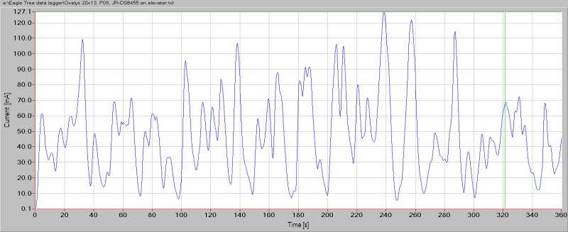
General : On all surfaces the general amperage was measured to be on a low but noisy level, the peak values are typically whenever an abrupt fast stick movement was done. This is to be expected from studying test-results, the highest consumption is not during static loads, or not even when moving a load, it's whenever a movement is initiated load or no load. By applying a filter (0.1[Hz] Low pass) to the data, as shown in the graphs on the right below, one sees a picture that more clearly presents the longer periods of load more similar to a static servo-load (aerodynamically load on the surfaces). Elevator : The peak values are during maneuver 9 and 17, the snap-rolls. The peak here is at around 400[mA], the same as the average current when moving with a 1[kgcm] load, not much at all. Typical examples of 'static' loads are found at 240 and 255[s] which is at the bottom of the two loops with integrated roll on top (maneuver 13). Even in these places the current is only 120[mA], as a comparison a static load of 0.5[kgcm] makes this servo consume 140[mA] !
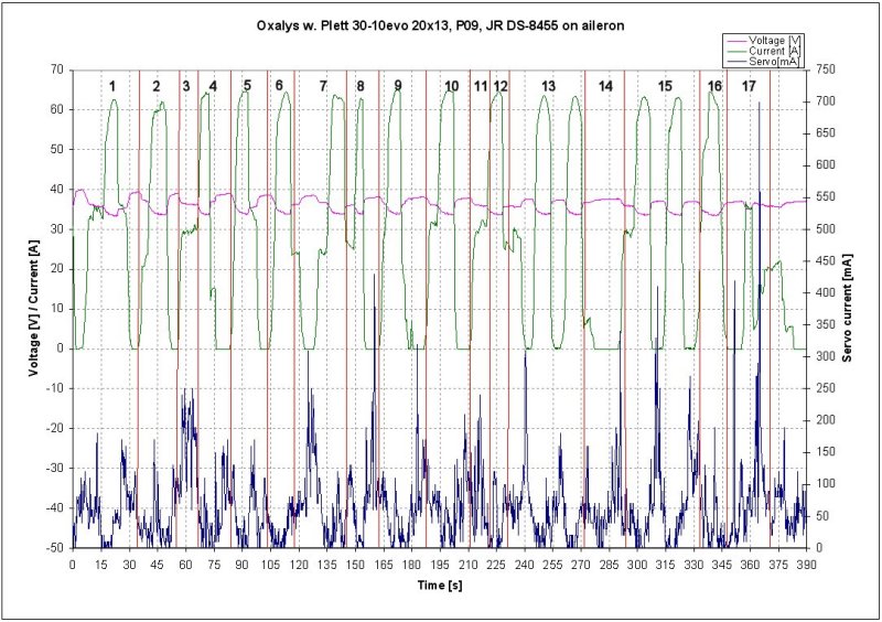
Ailerons : As with the elevator the general level is quite low, but a little higher than on elevator. Again the peaks are in places with abrupt movements, as during roll reversal in maneuver 8 (figure 9), the snaps (9 and 17) and the rolls in maneuver 15 (cuban 8). The filtered data shows the same more static-like loads as with the elevator, in the three rolls, 3/4 in the stall-turn etc. Again the general maximum is in the 130[mA] range, with an exception of in the 240[mA] during the final snap-roll.
Rudder : The rudder was the most exciting, as one has been told that blow-back is likely to happen. As expected the peaks during snap-rolls are slightly higher at around 600[mA] than for the other surfaces. Also during stall-turns an spin there are peaks of about 200-250[mA], nothing to worry about. The filtered data shows the same, with peaks during P09 of around 130[mA]. The final test is of course the KE-loop that shows a clear peak during entry and a major one when going down. The un-filtered show a smaller peak than during the snaps, while filtered data shows a peak of less than 400[mA]. To repeat myself, 400[mA] is the consumption with a static load of 1.5[kgcm] applied to the servo. 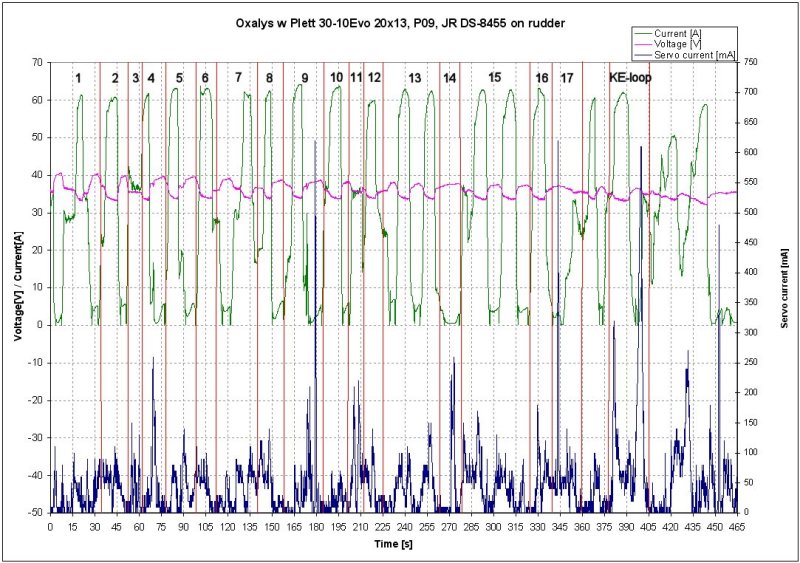

|

